Device identification
Backflow preventer diagram: use the layout to ask better service questions
A diagram helps label visible zones such as shutoffs, test cocks, checks, relief or vent paths, and unions.
A diagram helps label visible zones such as shutoffs, test cocks, checks, relief or vent paths, and unions. It does not establish the model, hazard classification, part compatibility, or repair method.
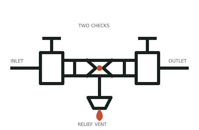
Use diagrams only for observation and communication. Escalate any active discharge, damage, failed test, or uncertain device identity.
Interactive check
Turn observations into a next step
This narrows the route. It does not replace an on-site test, manufacturer instructions, or local requirements.
Evidence sequence
Move in this order
- 01
Observe and identify
Take a full-device photo and identify visible components without disassembly.
- 02
Match the verified path
Use the diagram to describe where a symptom appears, then confirm the actual model.
- 03
Close the risk loop
Route to model-specific service, testing, or installation requirements based on verified identity.
Identification notes
What to look for
- The manufacturer label identifies the product; the diagram only describes a device family.
- Visible ports and covers can help communicate a leak location to a technician.
- System use and local requirements cannot be inferred from a simplified drawing.
Safe observations
What you can check without taking it apart
- Do not use a drawing to select a repair kit.
- Do not adjust screws or test ports based on a diagram.
- Keep safety and access boundaries visible in photos.
Stop conditions
Move to qualified help when
- The actual device does not match the assumed family.
- The diagram is being used to justify unverified service work.
Boundary check
Do not confuse this path with
- A product-family name alone does not establish component compatibility.
- A generic online part listing is not a repair diagnosis.
- This page does not replace a qualified on-site assessment.
Official local layer
Your utility sets the rule
Use exact manufacturer literature and the governing utility or authority record to validate the device, service path, and compliance closeout.
Evidence ledger
What this decision path is built on
Use exact manufacturer literature and the governing utility or authority record to validate the device, service path, and compliance closeout.
- 01U.S. EPA · EPA-CCC-001Cross-Connection Control ManualBackflow, backsiphonage, device families, hazard protection, testing, and program responsibility. Verified 2026-08-02.
- 02Watts · WATTS-RPZ-009Series 009 reduced pressure zone assemblyRPZ construction, relief discharge, installation constraints, service literature, and local-code warning. Verified 2026-08-02.
- 03USC Foundation for Cross-Connection Control and Hydraulic Research · USC-DEVICE-GUIDE-2026Cross-connection control introduction and assembly descriptionsAssembly descriptions and the requirement to check the local administrative authority for acceptable use; supports device-family comparison and fire-system distinction. Verified 2026-08-02.
Continue the case
Related next steps
CONTENT REVIEWED · 2026-08-02